")


Description
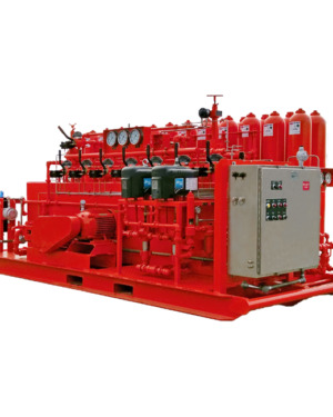
BOP closing unit ( koomey bop control unit )
BOP closing unit ( koomey bop control unit )
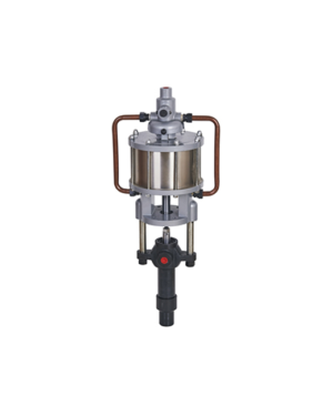
A BOP accumulator unit (also known as a BOP closing unit) is one of the most critical components of blow out preventers. Accumulators are placed in hydraulic systems for the purpose of storing energy to be released and transferred throughout the system when it is needed to accomplish specific operations. BOP accumulator units also provide hydraulic support when pressure fluctuations occur. These fluctuations happen often in positive displacement pumps due to their operational functions of trapping and displacing fluid.
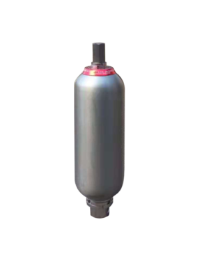
DEENPU’s BOP closing units are designed with service and reliability in mind, with bottles and bladders being easily accessible and serviceable. DEENPU’s modular design allows for future expansion and addition of bottles, so if your BOP closing unit specs change we can help you adapt.
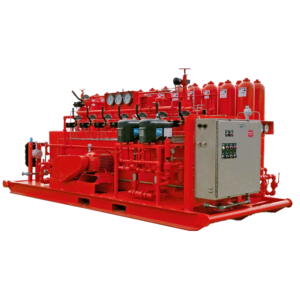
Each one of our BOP closing units is designed with absolute accuracy, providing safe and dependable command of the BOP stack for sustained operation, protecting you and your team from danger should a blowout occur. Our expert staff is ready to work with you to design and engineer the perfect BOP accumulator unit for your blowout prevention needs. At DEENPU, we take the time to work with you to size the unit to API-16D guidelines and build the unit to your unique requirements.
| Model | Number of controlled objects | Accumulator unit | Explosionproof motor Power (Kw) | ||
|---|---|---|---|---|---|
| Total volume (L) | Available liquid volume (L) | Installation mode | |||
| FKDQ1600-14 | 14 | 80×20 | 800 | Side/rear | 18.5×2 |
| FKDQ1600-12 | 12 | 80×20 | 800 | Side/rear | 18.5×2 |
| FKDQ1600-10 | 10 | 80×20 | 800 | Side/rear | 18.5×2 |
| FKDQ1440-14 | 14 | 60×24 | 720 | Side/rear | 18.5×2 |
| FKDQ1280-10 | 10 | 80×16 | 640 | Side/rear | 18.5×2 |
| FKDQ1280-9 | 9 | 80×16 | 640 | Side/rear | 18.5×2 |
| FKDQ1280-8 | 8 | 80×16 | 640 | Side/rear | 18.5×2 |
| FKDQ1280-7 | 7 | 80×16 | 640 | Side/rear | 18.5×2 |
| FKDQ1200-9 | 9 | 60×20 | 600 | Side/rear | 18.5×2 |
| FKDQ1200-8 | 8 | 60×20 | 600 | Side/rear | 18.5×2 |
| FKDQ960-8 | 8 | 60×16 | 480 | Side/rear | 18.5×2 |
| FKDQ960-7 | 7 | 60×16 | 480 | Side/rear | 18.5×2 |
| FKDQ800-8 | 8 | 40×20 | 400 | Side/rear | 18.5 |
| FKDQ 800-7 | 7 | 40×20 | 400 | Side/rear | 18.5 |
| FKDQ 800-6 | 6 | 40×20 | 400 | Side/rear | 18.5 |
| FKDQ720-7 | 7 | 60×12 | 360 | Side/rear | 18.5 |
| FKDQ 720-6 | 6 | 60×12 | 360 | Side/rear | 18.5 |
| FKDQ 640-6 | 6 | 40×16 | 320 | Side/rear | 18.5 |
| FKDQ 640-5 | 5 | 40×16 | 320 | Side/rear | 18.5 |
| FKDQ 480-5 | 5 | 40×12 | 240 | Side/rear | 18.5 |
| FKDQ 480-4 | 4 | 40×12 | 240 | Side/rear | 18.5 |
| FKDQ320-5 | 5 | 40×8 | 160 | Side/rear | 15 |
| FKDQ320-4 | 4 | 40×8 | 160 | Side/rear | 15 |
| FKDQ320-3 | 3 | 40×8 | 160 | Side/rear | 15 |
| FKDQ240-3 | 3 | 40×6 | 120 | Side/rear | 15 |
| FKDQ200-4 | 4 | 25×8 | 100 | Side/rear | 15 |
| FKDQ160-3 | 3 | 40×4 | 80 | Side/rear | 15 |
| FKDQ150-2 | 2 | 50×3 | 75 | Side/rear | 15 |
| FKDQ125-3 | 3 | 25×5 | 62.5 | Side/rear | 7.5/11 |
| FKDQ80-3 | 3 | 40×2 | 40 | Side/rear | 7.5 |
| FKDQ80-2 | 2 | 40×2 | 40 | Side/rear | 7.5 |
| FKDQ75-2 | 2 | 25×3 | 62.5 | Side/rear | 7.5 |
| FKDQ63-2 | 2 | 63×1 | 31.5 | Side/rear | 7.5 |
| FKDQ50-2 | 2 | 25×2 | 25 | Side/rear | 7.5 |
| FKDQ40-2 | 2 | 40×1 | 20 | Side/rear | 7.5 |
| FKDQ25-2 | 2 | 25×2 | 12.5 | Side/rear | 7.5 |
| FKDQ25-1 | 1 | 25×2 | 12.5 | Side/rear | 7.5 |
| Model | Pump system displacement | Rated operating pressure of the system (Mpa) | Maximum operating pressure of the system (Mpa) | |
|---|---|---|---|---|
| Triplex pump (mL/r) | Pneumatic pump (mL/ stroke) | |||
| FKDQ1600-14 | 80×2 | 120×4 | 21 | 31.5 |
| FKDQ1600-12 | 80×2 | 120×4 | 21 | 31.5 |
| FKDQ1600-10 | 80×2 | 120×4 | 21 | 31.5 |
| FKDQ1440-14 | 80×2 | 120×4 | 21 | 31.5 |
| FKDQ1280-10 | 80×2 | 120×3 | 21 | 31.5 |
| FKDQ1280-9 | 80×2 | 120×3 | 21 | 31.5 |
| FKDQ1280-8 | 80×2 | 120×2 | 21 | 31.5 |
| FKDQ1280-7 | 80×2 | 120×2 | 21 | 31.5 |
| FKDQ1200-9 | 80×2 | 120×3 | 21 | 31.5 |
| FKDQ1200-8 | 80×2 | 120×2 | 21 | 31.5 |
| FKDQ960-8 | 80×2 | 120×2 | 21 | 31.5 |
| FKDQ960-7 | 80×2 | 120×2 | 21 | 31.5 |
| FKDQ800-8 | 80 | 120 | 21 | 31.5 |
| FKDQ 800-7 | 80 | 120 | 21 | 31.5 |
| FKDQ 800-6 | 80 | 120 | 21 | 31.5 |
| FKDQ720-7 | 80 | 120 | 21 | 31.5 |
| FKDQ 720-6 | 80 | 120 | 21 | 31.5 |
| FKDQ 640-6 | 80 | 120 | 21 | 31.5 |
| FKDQ 640-5 | 80 | 120 | 21 | 31.5 |
| FKDQ 480-5 | 80 | 120 | 21 | 31.5 |
| FKDQ 480-4 | 80 | 120 | 21 | 31.5 |
| FKDQ320-5 | 60 | 120 | 21 | 31.5 |
| FKDQ320-4 | 60 | 120 | 21 | 31.5 |
| FKDQ320-3 | 60 | 120 | 21 | 31.5 |
| FKDQ240-3 | 60 | 120 | 21 | 31.5 |
| FKDQ200-4 | 60 | 120 | 21 | 31.5 |
| FKDQ160-3 | 60 | 120 | 21 | 31.5 |
| FKDQ150-2 | 60 | 120 | 21 | 31.5 |
| FKDQ125-3 | 28 | – | 21 | 21 |
| FKDQ80-3 | 28 | – | 21 | 21 |
| FKDQ80-2 | 28 | – | 21 | 21 |
| FKDQ75-2 | 28 | – | 21 | 21 |
| FKDQ63-2 | 28 | – | 21 | 21 |
| FKDQ50-2 | 28 | – | 21 | 21 |
| FKDQ40-2 | 28 | – | 21 | 21 |
| FKDQ25-2 | 28 | – | 21 | 21 |
| FKDQ25-1 | 28 | – | 21 | 21 |
Main Technical Parameters of Electric Hydraulic Control System
| Normal pressure of the system: | 21 Mpa | 3000 psi |
|---|---|---|
| Pressure regulating range of the system: | 0~14 Mpa | 3000 psi |
| Nitrogen charging pressure of accumulator: | 7±0.7 Mpa | 3000 psi |
| Pressure switch setting range: | 18.9~21 Mpa | 2700~3000psi |
| Hydraulic/pneumatic switch setting range: | 18.9~21 Mpa | 2700~3000psi |
| Air supply pressure: | 0.65~0.8 Mpa | 93~115psi |
| Power supply: | 380±19V / 50Hz Optional as required by customers |
|
| Control power supply: | 24V DC | |
| Battery capacity: | 10Ah | |
| Communication interface: | Profibus-Dp |
Functional Configuration of Electric Hydraulic Control System
| Model | Electric oil pump | Pneumatic oil pump | Manual oil pump | Alarm device | Standby nitrogen system | Protection house |
|---|---|---|---|---|---|---|
| FKDQ1600-14 | • | • | ◊ | • | ◊ | • |
| FKDQ1600-12 | • | • | ◊ | • | ◊ | • |
| FKDQ1600-10 | • | • | ◊ | • | ◊ | • |
| FKDQ1440-14 | • | • | ◊ | • | ◊ | • |
| FKDQ1280-10 | • | • | ◊ | • | ◊ | • |
| FKDQ1280-9 | • | • | ◊ | • | ◊ | • |
| FKDQ 1280-8 | • | • | ◊ | • | ◊ | • |
| FKDQ1280-7 | • | • | ◊ | • | ◊ | • |
| FKDQ1200-9 | • | • | ◊ | • | ◊ | • |
| FKDQ1200-8 | • | • | ◊ | • | ◊ | • |
| FKDQ960-8 | • | • | ◊ | • | ◊ | • |
| FKDQ960-7 | • | • | ◊ | • | ◊ | • |
| FKDQ800-8 | • | • | ◊ | • | ◊ | • |
| FKDQ 800-7 | • | • | ◊ | • | ◊ | • |
| FKDQ 800-6 | • | • | ◊ | • | ◊ | • |
| FKDQ720-7 | • | • | ◊ | • | ◊ | • |
| FKDQ 720-6 | • | • | ◊ | • | ◊ | • |
| FKDQ 640-6 | • | • | ◊ | • | ◊ | • |
| FKDQ 640-5 | • | • | ◊ | • | ◊ | • |
| FKDQ 480-5 | • | • | ◊ | • | ◊ | • |
| FKDQ 480-4 | • | • | ◊ | • | ◊ | • |
| FKDQ320-5 | • | • | ◊ | • | ◊ | • |
| FKDQ320-4 | • | • | ◊ | • | ◊ | • |
| FKDQ320-3 | • | • | ◊ | • | ◊ | • |
| FKDQ240-3 | • | • | ◊ | • | ◊ | • |
| FKDQ200-4 | • | • | ◊ | • | ◊ | • |
| FKDQ160-3 | • | • | ◊ | • | ◊ | • |
| FKDQ150-2 | • | • | ◊ | • | ◊ | • |
| FKDQ125-3 | • | x | ◊ | • | ◊ | • |
| FKDQ80-3 | • | x | ◊ | • | ◊ | • |
| FKDQ80-2 | • | x | ◊ | • | ◊ | • |
| FKDQ75-2 | • | x | ◊ | • | ◊ | • |
| FKDQ63-2 | • | x | ◊ | • | ◊ | • |
| FKDQ50-2 | • | x | ◊ | • | ◊ | • |
| FKDQ40-2 | • | x | ◊ | • | ◊ | • |
| FKDQ25-2 | • | x | ◊ | • | ◊ | • |
| FKDQ25-1 | • | x | ◊ | • | ◊ | • |
| Model | Insulated House | Driller’s console | Auxiliary console | Pipe rack and hose | PN-T automatic recording system | Zero pressure starting system |
|---|---|---|---|---|---|---|
| FKDQ1600-14 | ◊ | • | ◊ | ◊ | ◊ | ◊ |
| FKDQ1600-12 | ◊ | • | ◊ | ◊ | ◊ | ◊ |
| FKDQ1600-10 | ◊ | • | ◊ | ◊ | ◊ | ◊ |
| FKDQ1440-14 | ◊ | • | ◊ | ◊ | ◊ | ◊ |
| FKDQ1280-10 | ◊ | • | ◊ | ◊ | ◊ | ◊ |
| FKDQ1280-9 | ◊ | • | ◊ | ◊ | ◊ | ◊ |
| FKDQ 1280-8 | ◊ | • | ◊ | ◊ | ◊ | ◊ |
| FKDQ1280-7 | ◊ | • | ◊ | ◊ | ◊ | ◊ |
| FKDQ1200-9 | ◊ | • | ◊ | ◊ | ◊ | ◊ |
| FKDQ1200-8 | ◊ | • | ◊ | ◊ | ◊ | ◊ |
| FKDQ960-8 | ◊ | • | ◊ | ◊ | ◊ | ◊ |
| FKDQ960-7 | ◊ | • | ◊ | ◊ | ◊ | ◊ |
| FKDQ800-8 | ◊ | • | ◊ | ◊ | ◊ | ◊ |
| FKDQ 800-7 | ◊ | • | ◊ | ◊ | ◊ | ◊ |
| FKDQ 800-6 | ◊ | • | ◊ | ◊ | ◊ | ◊ |
| FKDQ720-7 | ◊ | • | ◊ | ◊ | ◊ | ◊ |
| FKDQ 720-6 | ◊ | • | ◊ | ◊ | ◊ | ◊ |
| FKDQ 640-6 | ◊ | • | ◊ | ◊ | ◊ | ◊ |
| FKDQ 640-5 | ◊ | • | ◊ | ◊ | ◊ | ◊ |
| FKDQ 480-5 | ◊ | • | ◊ | ◊ | ◊ | ◊ |
| FKDQ 480-4 | ◊ | • | ◊ | ◊ | ◊ | ◊ |
| FKDQ320-5 | ◊ | • | ◊ | ◊ | ◊ | ◊ |
| FKDQ320-4 | ◊ | • | ◊ | ◊ | ◊ | ◊ |
| FKDQ320-3 | ◊ | • | ◊ | ◊ | ◊ | ◊ |
| FKDQ240-3 | ◊ | • | ◊ | ◊ | ◊ | ◊ |
| FKDQ200-4 | ◊ | • | ◊ | ◊ | ◊ | ◊ |
| FKDQ160-3 | ◊ | • | ◊ | ◊ | ◊ | ◊ |
| FKDQ150-2 | ◊ | • | ◊ | ◊ | ◊ | ◊ |
| FKDQ125-3 | ◊ | • | ◊ | ◊ | ◊ | ◊ |
| FKDQ80-3 | ◊ | • | ◊ | ◊ | ◊ | ◊ |
| FKDQ80-2 | ◊ | • | ◊ | ◊ | ◊ | ◊ |
| FKDQ75-2 | ◊ | • | ◊ | ◊ | ◊ | ◊ |
| FKDQ63-2 | ◊ | • | ◊ | ◊ | ◊ | ◊ |
| FKDQ50-2 | ◊ | • | ◊ | ◊ | ◊ | ◊ |
| FKDQ40-2 | ◊ | • | ◊ | ◊ | ◊ | ◊ |
| FKDQ25-2 | ◊ | • | ◊ | ◊ | ◊ | ◊ |
| FKDQ25-1 | ◊ | • | ◊ | ◊ | ◊ | ◊ |
Note:
- Listed above are basic configurations of our products, where, “•” represents basic configuration and “◊” optional.
- The optional configuration here doesn’t mean that it is available in any model, which should be discussed at time of contract conclusion.
- Protection room width: 2100mm for common room and 2300mm for room with thermal insulation.
- Listed above are basic configurations, but special design and manufacturing can be provided upon request.
- The auxiliary driller’s console can be based on buttons or touch screen
- Pneumatic pump is not available to FKDQ series liquid control equipment. The remote console must be provided with air supply interface for pneumatic control.
-300x375.png)