
FC SMLR Gate Valve — API 6A, Full Bore Through Conduit, Slab Gate
2,000–20,000 PSI Working Pressure • 1-13/16"–7-1/16" Bore Size • Non-Rising Stem • Floating Slab Gate & Seats • Threaded & Flanged Ends
Product Overview
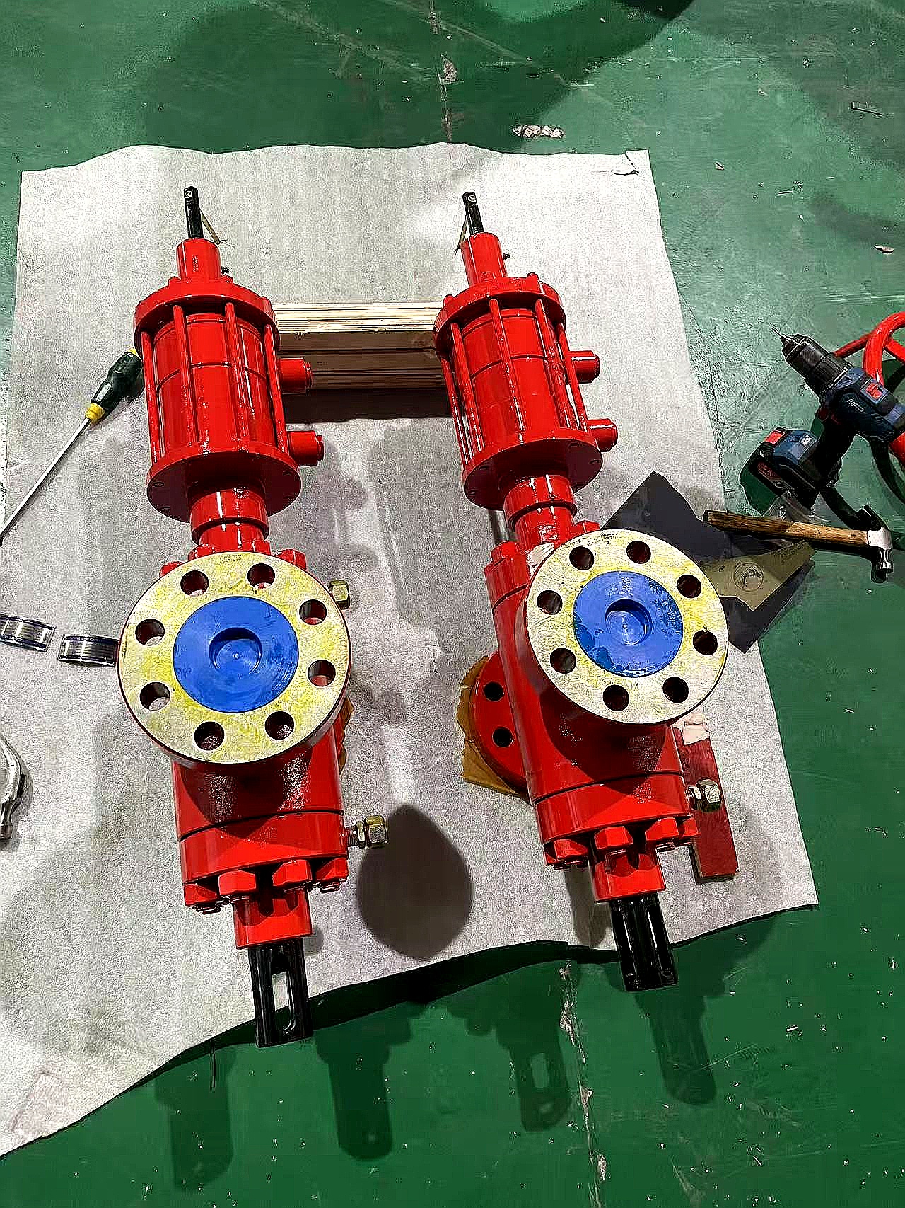
DEENPU FC SMLR Gate Valve — Full Bore Through Conduit Design with Non-Rising Stem and Floating Slab Gate
The DEENPU FC SMLR Gate Valve is a field-proven, API 6A compliant gate valve designed for wellhead, manifold, and production system applications in the oil and gas industry. The valve features a non-rising stem with a slab gate full bore through conduit design, providing a straight, unobstructed flow path when fully open that minimizes pressure drop and turbulence. The floating slab gate and floating seat ring body bushing design ensures safe, dependable service by allowing the gate and seats to self-align under pressure, providing uniform metal-to-metal sealing contact across the full sealing surface.
DEENPU FC SMLR Gate Valves are available in working pressures from 2,000 PSI (2M) through 20,000 PSI (20M) and bore sizes from 1-13/16″ through 7-1/16″, covering the full range of API 6A wellhead and manifold applications. The valve is available with both threaded end and flanged end connections, with dimensions and pressure ratings compliant with API 6A and ASME B16.5 standards. The non-rising stem design minimizes the operational space required above the valve, while the floating seat design allows for reliable sealing even under thermal expansion and pressure fluctuations.
A unique feature of the FC SMLR design is the stem pin shear protection — the stem pin is designed to shear if the hand wheel is over-torqued, protecting the stem and internal parts from failure. The one-piece slab gate helps prevent line sediment from entering the body cavity and prevents pressure locks when the upstream pressure drops. The valve is available in a wide range of body and trim materials to meet various operating conditions, including sweet service, sour service (H2S), and high-temperature applications.
How the FC SMLR Gate Valve Works
The FC SMLR gate valve operates through a unique floating slab gate mechanism that provides reliable sealing and long service life in demanding oilfield conditions:
- Full Bore Through Conduit Design — When the valve is fully open, the slab gate is completely retracted into the bonnet, leaving a straight, unobstructed bore through the valve body that matches the internal diameter of the connecting pipe. This full bore design provides several advantages: minimal pressure drop across the valve (typically less than 0.5 PSI at maximum flow rate), reduced turbulence and erosion of the valve internals, ability to pass pigs and scrapers through the valve for pipeline cleaning, and no flow restriction that could cause cavitation or vibration. The through conduit design is particularly important in production manifolds and pipeline applications where flow efficiency and pigging capability are critical. The slab gate is a single, flat piece of precision-machined steel that slides perpendicular to the flow direction, providing a simple, reliable sealing mechanism with minimal moving parts.
- Floating Slab Gate and Seat Design — Unlike conventional wedge gate valves where the gate is forced into the seats by stem torque, the FC SMLR uses a floating slab gate and floating seat rings. The gate is free to move slightly within the body cavity, and the seat rings are spring-loaded or pressure-energized to maintain contact with the gate. When the valve is closed, the line pressure acts on the gate and seats to push them together, creating a pressure-assisted seal. The floating design allows the gate and seats to self-align and compensate for thermal expansion, pressure deformation, and minor misalignment. This ensures uniform sealing contact across the full sealing surface, preventing the localized wear and leakage that can occur with rigid gate designs. The seat rings are fitted with O-rings or gaskets to seal against the body, and the metal-to-metal contact between the gate and seats provides the primary pressure seal. The floating design also allows for easy in-line maintenance: the gate and seat assembly can be removed and replaced without removing the valve from the line, using standard tools.
- Stem Pin Shear Protection and Back Seat Sealing — The FC SMLR features a stem pin that connects the hand wheel to the stem. If the operator applies excessive torque (e.g., by hammering on the hand wheel or using a cheater bar), the stem pin is designed to shear at a predetermined torque, preventing damage to the stem threads, gate, and seats. This is a critical safety feature that protects the valve from catastrophic failure due to over-torquing. The valve also features a stem back seat — a conical seal surface on the stem that pushes against the bonnet when the valve is fully open. This back seat creates a metal-to-metal seal that isolates the stem packing from the line pressure, allowing the stem seal (packing) to be replaced while the valve is still under pressure. This is an essential feature for production applications where the valve cannot be depressurized for maintenance. The stem back seat also provides a secondary seal in the event of packing failure, preventing external leakage and potential safety hazards.
Key Features
Applications
- Wellhead production valves — Master valve, wing valve, and swab valve on Christmas trees and wellhead assemblies for production flow control
- Choke and kill manifolds — Isolation valves on choke manifold, kill manifold, and well control system piping for high-pressure shutoff
- Production manifolds — Flowline isolation, header valves, and test line valves on production and test manifold systems
- Pipeline isolation — Full bore design allows pigging. Ideal for pipeline block valves, launcher/receiver valves, and station isolation
- Water injection systems — High-pressure isolation valves on water injection wellheads and injection manifold systems
- Gas lift systems — Gas lift manifold valves, gas supply line valves, and wellhead gas lift valves
- Well testing and workover — Temporary and permanent valves on test manifolds, workover BOP stacks, and well service lines
- High-pressure fracturing and stimulation — 10M, 15M, and 20M valves for fracturing manifold, stimulation lines, and high-pressure pumping systems
Flanged End FC SMLR Gate Valve Dimensions — 2,000 PSI
| Size | Bore (in / mm) |
A — Face to Face (in / mm) |
B — Centerline to Bottom (in / mm) |
C — Centerline to Handwheel Top (in / mm) |
D — Handwheel Diameter (in / mm) |
Weight (lb / kg) |
|---|---|---|---|---|---|---|
| 2-1/16″ | 2.06 / 52.4 | 11.61 / 295 | 5.31 / 135 | 20.87 / 530 | 13.98 / 355 | 176 / 80 |
| 2-9/16″ | 2.56 / 65.1 | 13.11 / 333 | 5.91 / 150 | 21.65 / 550 | 13.98 / 355 | 209 / 95 |
| 3-1/8″ | 3.13 / 79.4 | 14.13 / 359 | 7.48 / 190 | 22.44 / 570 | 16.93 / 430 | 220 / 100 |
| 4-1/16″ | 4.06 / 103.2 | 17.13 / 435 | 9.45 / 240 | 25.00 / 635 | 16.50 / 470 | 353 / 160 |
Flanged End FC SMLR Gate Valve Dimensions — 3,000 PSI
| Size | Bore (in / mm) |
A — Face to Face (in / mm) |
B — Centerline to Bottom (in / mm) |
C — Centerline to Handwheel Top (in / mm) |
D — Handwheel Diameter (in / mm) |
Weight (lb / kg) |
|---|---|---|---|---|---|---|
| 2-1/16″ | 2.06 / 52.4 | 14.61 / 371 | 5.31 / 135 | 21.65 / 550 | 13.98 / 355 | 176 / 80 |
| 2-9/16″ | 2.56 / 65.1 | 16.61 / 422 | 5.91 / 150 | 21.65 / 550 | 13.98 / 355 | 209 / 95 |
| 3-1/8″ | 3.13 / 79.4 | 17.13 / 435 | 6.89 / 175 | 23.22 / 590 | 16.93 / 430 | 276 / 125 |
| 4-1/16″ | 4.06 / 103.2 | 20.12 / 511 | 9.45 / 240 | 25.00 / 635 | 16.50 / 470 | 507 / 230 |
Flanged End FC SMLR Gate Valve Dimensions — 5,000 PSI
| Size | Bore (in / mm) |
A — Face to Face (in / mm) |
B — Centerline to Bottom (in / mm) |
C — Centerline to Handwheel Top (in / mm) |
D — Handwheel Diameter (in / mm) |
Weight (lb / kg) |
|---|---|---|---|---|---|---|
| 2-1/16″ | 2.06 / 52.4 | 14.61 / 371 | 5.51 / 140 | 21.46 / 545 | 13.98 / 355 | 176 / 80 |
| 2-9/16″ | 2.56 / 65.1 | 16.61 / 422 | 5.91 / 150 | 22.44 / 570 | 13.98 / 355 | 232 / 105 |
| 3-1/8″ | 3.13 / 79.4 | 18.62 / 473 | 7.48 / 190 | 22.64 / 575 | 16.93 / 430 | 342 / 155 |
| 4-1/16″ | 4.06 / 103.2 | 21.61 / 549 | 9.06 / 230 | 25.98 / 660 | 16.50 / 470 | 562 / 255 |
Flanged End FC SMLR Gate Valve Dimensions — 10,000 PSI
| Size | Bore (in / mm) |
A — Face to Face (in / mm) |
B — Centerline to Bottom (in / mm) |
C — Centerline to Handwheel Top (in / mm) |
D — Handwheel Diameter (in / mm) |
Weight (lb / kg) |
|---|---|---|---|---|---|---|
| 1-13/16″ | 1.81 / 46.0 | 18.27 / 464 | 5.12 / 130 | 21.85 / 555 | 13.98 / 355 | 198 / 90 |
| 2-1/16″ | 2.06 / 52.4 | 20.51 / 521 | 5.71 / 145 | 21.46 / 545 | 18.50 / 470 | 265 / 120 |
| 2-9/16″ | 2.56 / 65.1 | 22.24 / 565 | 6.69 / 170 | 22.44 / 570 | 18.50 / 470 | 309 / 140 |
| 3-1/8″ | 3.06 / 77.8 | 24.37 / 619 | 8.07 / 205 | 23.43 / 595 | 18.50 / 470 | 463 / 210 |
| 4-1/16″ | 4.06 / 103.2 | 26.38 / 670 | 10.04 / 255 | 26.33 / 670 | 24.00 / 610 | 794 / 360 |
Flanged End FC SMLR Gate Valve Dimensions — 15,000 PSI
| Size | Bore (in / mm) |
A — Face to Face (in / mm) |
B — Centerline to Bottom (in / mm) |
C — Centerline to Handwheel Top (in / mm) |
D — Handwheel Diameter (in / mm) |
Weight (lb / kg) |
|---|---|---|---|---|---|---|
| 1-13/16″ | 1.81 / 46.0 | 17.99 / 457 | 5.31 / 135 | 21.65 / 550 | 18.50 / 470 | 231 / 105 |
| 2-1/16″ | 2.06 / 52.4 | 19.02 / 483 | 6.69 / 170 | 21.65 / 550 | 18.50 / 470 | 265 / 120 |
| 3-1/16″ | 3.06 / 77.8 | 23.54 / 598 | 8.86 / 225 | 27.76 / 705 | 24.00 / 610 | 705 / 320 |
| 4-1/16″ | 4.06 / 103.2 | 29.02 / 737 | 10.24 / 260 | 29.54 / 750 | 24.00 / 610 | 1,058 / 480 |
All dimensions approximate per API 6A 21st Edition. Flange face-to-face dimensions vary with flange type (6B vs 6BX) and ring gasket type. Weights shown are approximate for standard carbon steel construction. Contact us for exact dimensions, weights for alternative materials, and custom configurations. 20M (20,000 PSI) ratings available on request for selected sizes.
Threaded End FC SMLR Gate Valve Dimensions — 2,000 PSI
| Size | Bore (in / mm) |
A — Face to Face (in / mm) |
B — Centerline to Bottom (in / mm) |
C — Centerline to Handwheel Top (in / mm) |
D — Handwheel Diameter (in / mm) |
Weight (lb / kg) |
|---|---|---|---|---|---|---|
| 2-1/16″ | 2.06 / 52.4 | 11.61 / 295 | 4.92 / 125 | 18.50 / 470 | 11.02 / 280 | 99 / 45 |
| 2-9/16″ | 2.56 / 65.1 | 12.20 / 310 | 5.91 / 150 | 19.09 / 485 | 12.99 / 330 | 143 / 65 |
| 3-1/8″ | 3.13 / 79.4 | 13.39 / 340 | 7.48 / 190 | 21.65 / 550 | 12.99 / 330 | 220 / 100 |
| 4-1/16″ | 4.06 / 103.2 | 14.96 / 380 | 7.13 / 435 | 16.73 / 425 | 15.94 / 405 | 353 / 160 |
Threaded End FC SMLR Gate Valve Dimensions — 3,000 PSI
| Size | Bore (in / mm) |
A — Face to Face (in / mm) |
B — Centerline to Bottom (in / mm) |
C — Centerline to Handwheel Top (in / mm) |
D — Handwheel Diameter (in / mm) |
Weight (lb / kg) |
|---|---|---|---|---|---|---|
| 2-1/16″ | 2.06 / 52.4 | 14.61 / 371 | 5.31 / 135 | 21.65 / 550 | 13.98 / 355 | 132 / 60 |
| 2-9/16″ | 2.56 / 65.1 | 12.20 / 310 | 5.91 / 150 | 21.65 / 550 | 13.98 / 355 | 143 / 65 |
| 3-1/8″ | 3.13 / 79.4 | 13.39 / 340 | 7.48 / 190 | 22.44 / 570 | 16.93 / 430 | 220 / 100 |
| 4-1/16″ | 4.06 / 103.2 | 14.96 / 380 | 9.45 / 240 | 25.00 / 635 | 18.50 / 470 | 353 / 160 |
Threaded End FC SMLR Gate Valve Dimensions — 5,000 PSI
| Size | Bore (in / mm) |
A — Face to Face (in / mm) |
B — Centerline to Bottom (in / mm) |
C — Centerline to Handwheel Top (in / mm) |
D — Handwheel Diameter (in / mm) |
Weight (lb / kg) |
|---|---|---|---|---|---|---|
| 2-1/16″ | 2.06 / 52.4 | 9.65 / 245 | 5.31 / 135 | 21.65 / 550 | 13.98 / 355 | 132 / 60 |
| 2-9/16″ | 2.56 / 65.1 | 12.20 / 310 | 5.91 / 150 | 21.65 / 550 | 13.98 / 355 | 154 / 70 |
| 3-1/8″ | 3.13 / 79.4 | 13.39 / 340 | 7.48 / 190 | 23.23 / 590 | 16.93 / 430 | 198 / 90 |
| 4-1/16″ | 4.06 / 103.2 | 14.96 / 380 | 9.06 / 230 | 25.98 / 660 | 18.50 / 470 | 287 / 130 |
Threaded end connections: API line pipe or tubing threads. A = Thread face to face. B = Bore centerline to bottom of valve. C = Bore centerline to handwheel top. D = Handwheel diameter. All dimensions per API 6A. Contact us for non-standard sizes and custom configurations.
When Ordering, Please Specify
- Valve SizeStandard bore sizes: 1-13/16″, 2-1/16″, 2-9/16″, 3-1/8″, 3-1/16″, 4-1/16″. Custom sizes available on request.
- Working Pressure Rating2M (2,000 PSI), 3M (3,000 PSI), 5M (5,000 PSI), 10M (10,000 PSI), 15M (15,000 PSI), or 20M (20,000 PSI). Select based on maximum anticipated operating pressure.
- End Connection TypeThreaded end (API line pipe or tubing thread) or flanged end (API 6B or 6BX flange). Specify thread type or flange size and pressure rating.
- Ring Gasket Type (for flanged valves)BX (for 6BX flanges), RX (for 6B flanges), or R (for type 6B flanges). Specify based on mating flange configuration.
- Material GradeAPI 6A material grade: AA, BB, CC, DD, EE, FF, or HH. For sour service, specify NACE MR0175 compliant grade. For low-temperature service, specify impact test requirements.
- Material SpecificationCarbon steel (AISI 4130/4140), low-alloy steel, or stainless steel (duplex, super duplex). Specify for corrosive or high-temperature environments.
- Trim MaterialGate and seat trim material: 410 SS, 316 SS, Inconel, or Stellite hardfacing. Specify for abrasive or corrosive service.
- Operator TypeHandwheel (standard), chainwheel (for elevated installations), gear operator (for high-torque or motor actuation), or pneumatic/hydraulic actuator.
- Service ConditionGeneral (sweet) service or Sour Service (H2S). Specify H2S partial pressure, CO2 content, and temperature for sour service material selection.
- Certification RequirementsAPI 6A certification, material test certificates (MTC), hydrostatic test certificates (shell and seat), NACE MR0175 compliance certificate, and third-party inspection (DNV, BV, SGS).
Custom Manufacturing & OEM Capability
- Non-Standard Sizes — Custom bore sizes, face-to-face dimensions, and overall dimensions manufactured to customer specifications for retrofit and replacement applications.
- Special Material Grades — Duplex stainless steel (2205, 2507), super duplex, Inconel, Monel, and other corrosion-resistant alloys for extreme sour service and high-temperature applications.
- Actuator-Ready Configuration — Valve prepared for pneumatic, hydraulic, or electric actuator mounting with ISO 5210 mounting flange, stem extension, and position indicator.
- Locking and Safety Devices — Stem locking devices, mechanical stop locks, and safety interlocks for critical isolation applications where accidental operation must be prevented.
- Extended Bonnet / Cryogenic Service — Extended bonnet design for cryogenic service, LNG applications, and extreme cold environments to prevent stem packing freeze-up.
- Special Coating and Surface Treatment — Internal cladding (Inconel 625 or 316L overlay), PTFE coating, epoxy coating, or hard chrome plating for corrosion resistance and reduced friction.
- Special Testing — Gas testing (helium or nitrogen leak test), cryogenic testing, fire-safe testing (API 6FA), and high-cycle endurance testing beyond standard API 6A requirements.
- Complete Valve Package — Valve supplied as part of a complete wellhead assembly including casing heads, tubing heads, Christmas trees, and manifolds.
Quality Control & Testing Standards
- Material chemical composition verified per heat. Carbon, manganese, chromium, nickel, molybdenum, and sulfur content verified against API 6A material grade requirements.
- Material mechanical properties tested per heat including tensile strength, yield strength, elongation, and hardness per API 6A.
- Impact testing at specified temperature for low-temperature service per API 6A and ASTM A370.
- Each valve shell hydrostatically tested to 1.5x rated working pressure per API 6A. Hold time and leak rate recorded on test certificate.
- Each valve seat hydrostatically tested to 1.1x rated working pressure in both directions. Zero leakage acceptance criterion.
- Gas seat test (optional) at 80% of rated working pressure using nitrogen or helium for critical applications. Leak detection by bubble test or pressure decay.
- Dimensional inspection of bore diameter, face-to-face dimension, flange dimensions, handwheel diameter, and overall height per API 6A tolerances.
- Gate and seat contact surface inspection with dye penetrant or magnetic particle inspection to verify integrity of sealing surfaces.
- Stem thread and thrust bearing inspection for proper fit, torque, and smooth rotation.
- Material test certificates (MTC) per EN 10204 3.1 provided for all valve body, bonnet, gate, and seat materials.
- Third-party inspection and certification by DNV, BV, SGS, or ABS available upon request.
Frequently Asked Questions
What is the difference between a slab gate valve and a wedge gate valve?
A wedge gate valve uses a wedge-shaped gate that is forced into tapered seats by the stem torque. The wedge design provides a mechanical sealing force that is independent of line pressure, but it can be difficult to open under high differential pressure because the wedge is forced tightly into the seats. The wedge design also tends to trap solids in the body cavity, which can cause pressure locking and prevent the valve from opening. A slab gate valve (like the FC SMLR) uses a flat, rectangular gate that slides between two parallel seats. The gate is not wedged into the seats; instead, the seats are spring-loaded or pressure-energized to maintain contact with the gate. The slab gate design provides several advantages: (1) lower operating torque because the gate is not wedged into the seats; (2) no pressure locking because the gate is flat and does not trap solids in the body cavity; (3) full bore through conduit design that matches the pipe ID for minimal pressure drop and pigging capability; (4) bi-directional sealing because the floating seats can seal against pressure from either direction. The slab gate design is the preferred choice for high-pressure wellhead and manifold applications where reliable shutoff and low operating torque are critical.
What is the advantage of a full bore through conduit design?
A full bore through conduit design means that when the valve is fully open, the internal bore of the valve matches the internal diameter of the connecting pipe, creating a straight, unobstructed flow path with no restrictions, cavities, or pockets. The advantages are: (1) Minimal pressure drop — the pressure loss across the valve is typically less than 0.5 PSI at maximum flow rate, which is critical for production efficiency in high-flow-rate wells and pipelines. (2) Reduced turbulence and erosion — the smooth flow path minimizes turbulence, cavitation, and erosion of the valve internals, extending the service life of the valve and downstream equipment. (3) Pigging capability — the full bore allows pipeline pigs, scrapers, and inspection tools to pass through the valve without obstruction. This is essential for pipeline maintenance, cleaning, and inline inspection (ILI) operations. (4) No sediment trapping — the straight bore prevents solids, sand, and sediment from accumulating in the valve body, which can cause valve malfunction and pressure locking. (5) Low noise and vibration — the unobstructed flow path reduces flow-induced noise and vibration, which is important for offshore platforms and populated areas. The full bore design is the industry standard for pipeline block valves, production manifold valves, and any application where flow efficiency and pigging capability are required.
What is the purpose of the stem pin shear protection?
The stem pin is a small, precisely machined pin that connects the hand wheel to the stem in the FC SMLR gate valve. It is designed to shear (break) at a predetermined torque that is below the damage threshold of the stem threads, gate, and seats. If an operator applies excessive torque to the hand wheel (e.g., by hammering on the hand wheel, using a cheater bar, or attempting to force the valve open against a blocked line), the stem pin will shear before the valve internals are damaged. This protects the valve from catastrophic failure and allows for easy repair: the sheared pin can be replaced without removing the valve from the line or disassembling the valve internals. The stem pin is a sacrificial component that acts as a mechanical fuse, preventing expensive damage to the valve body, bonnet, stem, and gate. The shear torque of the pin is carefully calibrated to provide protection without interfering with normal valve operation. After a pin shear event, the valve should be inspected for the cause of the over-torque (e.g., blocked line, damaged gate, or debris in the body cavity) before replacing the pin and returning the valve to service.
What is the stem back seat and why is it important?
The stem back seat is a conical sealing surface machined on the stem that mates with a corresponding conical surface in the bonnet. When the valve is fully open, the back seat surfaces make contact and create a metal-to-metal seal that isolates the stem packing from the line pressure. This is important for several reasons: (1) Packing replacement under pressure — if the stem packing begins to leak, the valve can be fully opened to engage the back seat, which seals off the pressure from the packing area. The packing can then be replaced or tightened while the valve is still under pressure, without requiring system shutdown or depressurization. This is a critical feature for production valves that cannot be shut down for maintenance. (2) Secondary seal — the back seat provides a secondary seal in the event of packing failure, preventing external leakage and potential safety hazards. (3) Protection of packing from process fluid — when the back seat is engaged, the packing is isolated from the process fluid, which extends the life of the packing by preventing chemical attack, erosion, and temperature damage. (4) Stem retention — the back seat helps retain the stem in the bonnet in the event of a catastrophic packing failure, preventing the stem from being ejected by line pressure. The back seat is a standard feature on all FC SMLR gate valves and is an essential safety and maintenance feature for high-pressure oilfield applications.
What is the difference between threaded end and flanged end gate valves?
Threaded end gate valves have internal or external threads on the valve body ends that mate with threaded pipe or tubing connections. They are typically used for smaller sizes (2-1/16″ to 4-1/16″) and lower pressure ratings (2M, 3M, and 5M). Threaded end valves are lighter, more compact, and less expensive than flanged valves. They are commonly used in wellhead Christmas trees, small-bore manifold lines, and applications where space and weight are critical. The main disadvantage is that the threaded connection is not as robust as a flange for high-pressure or high-vibration service, and the threads can be damaged during make-up and break-out. Flanged end gate valves have API 6B or 6BX flanges on both ends that mate with matching flanges on the piping system using ring gaskets and stud bolts. Flanged valves are used for all sizes and pressure ratings, but they are especially common for larger sizes (4-1/16″ and above) and higher pressures (5M, 10M, 15M, and 20M). Flanged connections are more robust, easier to assemble and disassemble, and provide a more reliable seal for high-pressure and critical service. The main disadvantage is the increased weight, size, and cost. The face-to-face dimension of flanged valves is also larger than threaded valves, which must be considered in piping layout.
What certifications do your FC SMLR gate valves carry?
DEENPU FC SMLR Gate Valves are manufactured in accordance with API 6A (Specification for Wellhead and Christmas Tree Equipment). Each valve is supplied with a comprehensive documentation package including: material test certificate (chemical composition and mechanical properties), heat treatment certificate, hydrostatic test certificate (shell test at 1.5x working pressure and seat test at 1.1x working pressure), dimensional inspection report, and NDT reports (MPI/UT on castings and forgings). For Sour Service applications, a NACE MR0175 / ISO 15156 compliance certificate is provided. Material traceability is maintained from raw material through forging, heat treatment, machining, assembly, testing, and final inspection. Each valve is serialized and marked with the API monogram (when licensed), serial number, heat number, pressure rating, and material grade. Third-party inspection and certification by DNV, BV, SGS, or ABS is available on request for projects requiring classification society approval or customer-specific quality assurance protocols. DEENPU maintains an API Q1 quality management system and is certified for API 6A manufacturing.
Request a Quote — FC SMLR Gate Valve
Send your wellhead or manifold valve specifications and we will recommend the optimal FC SMLR gate valve configuration with a complete proposal including pricing, delivery schedule, and test certificates within 48 hours.
- EMAILSALES@DEENPU-MACHINERY.COM
- WHATSAPP+86-15806284962
- RESPONSEQuotation within 48 hours
Include: Valve size, pressure rating, end connection type (threaded or flanged), flange size and rating (if flanged), material grade, trim material, service condition (general or sour), and quantity.
About Us
 Our company has been in the oil & gas drilling equipment industry for over more years, We are here to serve all your drilling equipment needs.