
Model M Expanding Gate Valve — API 6A, Threaded & Flanged Ends
2-1/16"–7-1/16" Bore Size • 2,000–5,000 PSI Working Pressure • Expanding Gate Design • Non-Rising Stem • Roller Thrust Bearings
Product Overview
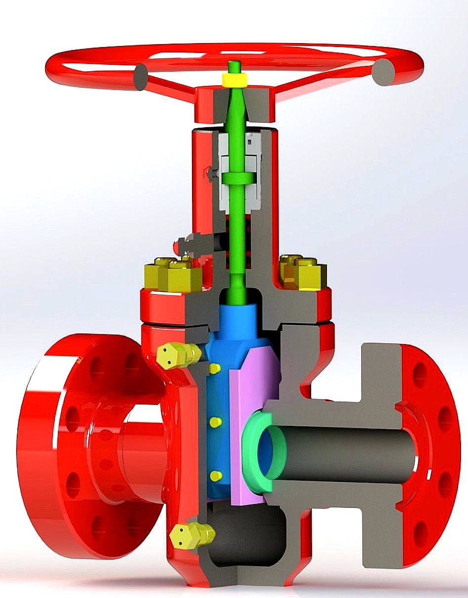
DEENPU Model M Expanding Gate Valve — 3D Cross-Section Showing Internal Components
The DEENPU Model M Series Expanding Gate Valve is a high-performance, API 6A compliant gate valve designed for wellhead, manifold, and production system applications in the oil and gas industry. The valve features a unique expanding gate design consisting of a gate body and a related segment, with the middle contact surface precision-machined to a milled V-Structure. This expanding mechanism ensures a tight, pressure-assisted seal between the gate and seats in both the open and closed positions, providing reliable shutoff and long service life in demanding oilfield conditions.
DEENPU Model M Gate Valves are available in bore sizes from 2-1/16″ through 7-1/16″ and working pressures from 2,000 PSI (2M) through 5,000 PSI (5M), covering the full range of standard API 6A wellhead and manifold applications. The valve is available with both threaded end and flanged end connections, with dimensions and pressure ratings compliant with API 6A and ASME B16.5 standards. The non-rising stem design minimizes the operational space required above the valve, while the upper and lower roller thrust bearings significantly reduce the operating torque required to open and close the valve under pressure.
Each valve is designed and manufactured to meet or exceed API 6A specification requirements, with full material traceability, hydrostatic testing, and comprehensive inspection documentation. The seats are fitted with grease injection fittings for in-service lubrication, reducing abrasion and extending the service life of the sealing surfaces. DEENPU Model M Gate Valves are suitable for both sweet (general) service and sour service (H2S) applications when manufactured with appropriate material grades and NACE MR0175 compliance.
How the Model M Expanding Gate Valve Works
The Model M expanding gate valve operates through a unique mechanism that provides superior sealing performance compared to conventional wedge gate valves:
- Expanding Gate Mechanism — The valve consists of two main components: the gate body and the gate segment. The contact surface between the gate body and segment is machined to a precision V-Structure. When the valve is in the closed position, the gate is positioned between the two seats, and the internal pressure of the fluid acts on the gate to push the gate body and segment apart, expanding the gate against the seats. This pressure-assisted expansion creates a tight, bubble-tight seal that improves as the line pressure increases. The V-Structure design ensures that the expansion force is evenly distributed across the full sealing surface, preventing localized wear and ensuring consistent sealing performance over thousands of cycles.
- Non-Rising Stem Operation — The Model M features a non-rising stem design, meaning the stem does not move vertically out of the valve bonnet when the valve is opened or closed. Instead, the stem rotates, and the gate moves up and down internally. This design provides several advantages: it minimizes the vertical space required above the valve, making it ideal for installations with limited overhead clearance (such as on offshore platforms and in crowded manifold assemblies); it prevents the stem from being exposed to the external environment, reducing the risk of corrosion and contamination; and it allows the valve to be operated in any orientation without the stem protruding. The non-rising stem is threaded into the gate and guided by a stem nut in the bonnet, with the upper and lower roller thrust bearings carrying the axial load and minimizing friction.
- Seat Lubrication and Wear Protection — The valve seats are equipped with grease injection fittings that allow the injection of seat lubricant (typically a valve sealant or lubricant compound) directly into the seat area. This lubrication serves three purposes: it reduces the friction between the gate and seats during operation, lowering the operating torque; it protects the sealing surfaces from abrasion and galling, particularly in applications with abrasive fluids or sand production; and it provides a secondary seal that can help maintain tight shutoff even if the primary metal-to-metal seal shows minor wear. The grease injection system can be serviced while the valve is in line, without requiring valve removal or system shutdown. Regular lubrication is recommended as part of the valve maintenance program to ensure long-term reliable performance.
Key Features
Applications
- Wellhead production valves — Master valve, wing valve, and swab valve on Christmas trees and wellhead assemblies for production flow control
- Choke and kill manifolds — Isolation valves on choke manifold, kill manifold, and well control system piping for high-pressure shutoff
- Production manifolds — Flowline isolation, header valves, and test line valves on production and test manifold systems
- Water injection systems — High-pressure isolation valves on water injection wellheads and injection manifold systems
- Gas lift systems — Gas lift manifold valves, gas supply line valves, and wellhead gas lift valves
- Well testing and workover — Temporary and permanent valves on test manifolds, workover BOP stacks, and well service lines
- Offshore platform wellheads — Compact, low-overhead valves on platform wellheads, subsea wellheads, and FPSO turret manifolds
- Gas processing and transmission — High-pressure isolation on gas gathering lines, compressor station piping, and gas processing plant headers
Threaded End Model M Gate Valve Dimensions — 2,000 PSI
| Size | Bore (in / mm) |
A — Face to Face (in / mm) |
B — Centerline to Bottom (in / mm) |
C — Centerline to Handwheel Top (in / mm) |
D — Handwheel Diameter (in / mm) |
Weight (lb / kg) |
|---|---|---|---|---|---|---|
| 2-1/16″ | 2.06 / 52.4 | 9.63 / 245 | 4.92 / 125 | 18.70 / 475 | 11.02 / 280 | 99 / 45 |
| 2-9/16″ | 2.56 / 65.1 | 10.25 / 260 | 5.91 / 150 | 19.09 / 485 | 12.99 / 330 | 132 / 60 |
| 3-1/8″ | 3.13 / 79.4 | 11.42 / 290 | 7.48 / 190 | 21.65 / 550 | 12.99 / 330 | 198 / 90 |
| 4-1/16″ | 4.06 / 103.2 | 12.99 / 330 | 8.86 / 225 | 24.61 / 625 | 12.99 / 330 | 276 / 125 |
Threaded end connections: API line pipe or tubing threads. A = Thread face to face. B = Bore centerline to bottom of valve. C = Bore centerline to hand wheel top. D = Hand wheel diameter. All dimensions per API 6A. Contact us for non-standard sizes and custom configurations.
Threaded End Model M Gate Valve Dimensions — 3,000 PSI
| Size | Bore (in / mm) |
A — Face to Face (in / mm) |
B — Centerline to Bottom (in / mm) |
C — Centerline to Handwheel Top (in / mm) |
D — Handwheel Diameter (in / mm) |
Weight (lb / kg) |
|---|---|---|---|---|---|---|
| 2-1/16″ | 2.06 / 52.4 | 9.63 / 245 | 4.92 / 125 | 18.70 / 475 | 12.99 / 330 | 110 / 50 |
| 2-9/16″ | 2.56 / 65.1 | 10.25 / 260 | 6.10 / 155 | 19.29 / 490 | 15.75 / 400 | 143 / 65 |
| 3-1/8″ | 3.13 / 79.4 | 11.42 / 290 | 7.48 / 190 | 21.65 / 550 | 15.75 / 400 | 198 / 90 |
| 4-1/16″ | 4.06 / 103.2 | 12.99 / 330 | 8.86 / 225 | 24.61 / 625 | 15.75 / 400 | 276 / 125 |
Threaded End Model M Gate Valve Dimensions — 5,000 PSI
| Size | Bore (in / mm) |
A — Face to Face (in / mm) |
B — Centerline to Bottom (in / mm) |
C — Centerline to Handwheel Top (in / mm) |
D — Handwheel Diameter (in / mm) |
Weight (lb / kg) |
|---|---|---|---|---|---|---|
| 2-1/16″ | 2.06 / 52.4 | 9.63 / 245 | 4.92 / 125 | 18.70 / 475 | 12.99 / 330 | 110 / 50 |
| 2-9/16″ | 2.56 / 65.1 | 10.25 / 260 | 5.90 / 150 | 19.29 / 490 | 15.75 / 400 | 144 / 65 |
| 3-1/8″ | 3.13 / 79.4 | 11.42 / 290 | 7.48 / 190 | 21.65 / 550 | 15.75 / 400 | 198 / 90 |
| 4-1/16″ | 4.06 / 103.2 | 12.99 / 330 | 8.86 / 225 | 24.61 / 625 | 15.75 / 400 | 276 / 125 |
Flanged End Model M Gate Valve Dimensions — 2,000 PSI
| Size | Bore (in / mm) |
A — Face to Face (in / mm) |
B — Centerline to Bottom (in / mm) |
C — Centerline to Handwheel Top (in / mm) |
D — Handwheel Diameter (in / mm) |
Weight (lb / kg) |
|---|---|---|---|---|---|---|
| 2-1/16″ | 2.06 / 52.4 | 11.61 / 295 | 4.92 / 125 | 18.50 / 470 | 11.02 / 280 | 99 / 45 |
| 2-9/16″ | 2.56 / 65.1 | 13.11 / 333 | 5.91 / 150 | 19.09 / 485 | 12.99 / 330 | 143 / 65 |
| 3-1/8″ | 3.13 / 79.4 | 14.13 / 359 | 7.48 / 190 | 21.65 / 550 | 12.99 / 330 | 220 / 100 |
| 4-1/16″ | 4.06 / 103.2 | 17.13 / 435 | 9.45 / 240 | 25.00 / 635 | 15.94 / 405 | 353 / 160 |
Flanged end connections: API 6B or 6BX flanges. A = Flange face to face. B = Bore centerline to bottom of valve. C = Bore centerline to hand wheel top. D = Hand wheel diameter. Ring gasket type: BX for 6BX flanges, RX for 6B flanges. All dimensions per API 6A.
Flanged End Model M Gate Valve Dimensions — 3,000 PSI
| Size | Bore (in / mm) |
A — Face to Face (in / mm) |
B — Centerline to Bottom (in / mm) |
C — Centerline to Handwheel Top (in / mm) |
D — Handwheel Diameter (in / mm) |
Weight (lb / kg) |
|---|---|---|---|---|---|---|
| 2-1/16″ | 2.06 / 52.4 | 14.61 / 371 | 5.31 / 135 | 18.70 / 475 | 12.99 / 330 | 110 / 50 |
| 2-9/16″ | 2.56 / 65.1 | 16.61 / 422 | 5.91 / 150 | 19.29 / 490 | 12.99 / 330 | 209 / 95 |
| 3-1/8″ | 3.13 / 79.4 | 17.13 / 435 | 7.48 / 190 | 21.65 / 550 | 15.75 / 400 | 331 / 150 |
| 4-1/16″ | 4.06 / 103.2 | 20.12 / 511 | 9.45 / 240 | 25.00 / 635 | 18.90 / 480 | 573 / 260 |
| 7-1/16″ | 7.06 / 179.4 | 28.11 / 714 | 13.98 / 355 | 32.48 / 825 | 29.92 / 760 | 1,235 / 560 |
Flanged End Model M Gate Valve Dimensions — 5,000 PSI
| Size | Bore (in / mm) |
A — Face to Face (in / mm) |
B — Centerline to Bottom (in / mm) |
C — Centerline to Handwheel Top (in / mm) |
D — Handwheel Diameter (in / mm) |
Weight (lb / kg) |
|---|---|---|---|---|---|---|
| 2-1/16″ | 2.06 / 52.4 | 14.61 / 371 | 5.11 / 130 | 18.70 / 475 | 12.99 / 330 | 110 / 50 |
| 2-9/16″ | 2.56 / 65.1 | 16.61 / 422 | 5.91 / 150 | 19.29 / 490 | 15.75 / 400 | 232 / 105 |
| 3-1/8″ | 3.13 / 79.4 | 18.62 / 473 | 7.48 / 190 | 21.65 / 550 | 15.75 / 400 | 331 / 150 |
| 4-1/16″ | 4.06 / 103.2 | 21.61 / 549 | 9.45 / 240 | 25.00 / 635 | 18.90 / 480 | 617 / 280 |
| 7-1/16″ | 7.06 / 179.4 | 32.01 / 813 | 13.98 / 355 | 32.48 / 825 | 29.92 / 760 | 1,323 / 600 |
All dimensions approximate per API 6A 21st Edition. Flange face-to-face dimensions vary with flange type (6B vs 6BX) and ring gasket type. Weights shown are approximate for standard carbon steel construction. Contact us for exact dimensions, weights for alternative materials (stainless steel, duplex, etc.), and custom configurations.
When Ordering, Please Specify
- Valve SizeStandard bore sizes: 2-1/16″, 2-9/16″, 3-1/8″, 4-1/16″, or 7-1/16″. Custom sizes available on request.
- Working Pressure Rating2M (2,000 PSI), 3M (3,000 PSI), or 5M (5,000 PSI). Select based on maximum anticipated operating pressure.
- End Connection TypeThreaded end (API line pipe or tubing thread) or flanged end (API 6B or 6BX flange). Specify thread type or flange size and pressure rating.
- Ring Gasket Type (for flanged valves)BX (for 6BX flanges), RX (for 6B flanges), or R (for type 6B flanges). Specify based on mating flange configuration.
- Material GradeAPI 6A material grade: AA, BB, CC, DD, EE, FF, or HH. For sour service, specify NACE MR0175 compliant grade. For low-temperature service, specify impact test requirements.
- Material SpecificationCarbon steel (AISI 4130/4140), low-alloy steel, or stainless steel (duplex, super duplex). Specify for corrosive or high-temperature environments.
- Stem ConfigurationNon-rising stem (standard for Model M). Rising stem available on special request. Specify handwheel or chainwheel operator.
- Operator TypeHandwheel (standard), chainwheel (for elevated installations), gear operator (for high-torque or motor actuation), or pneumatic/hydraulic actuator.
- Service ConditionGeneral (sweet) service or Sour Service (H2S). Specify H2S partial pressure, CO2 content, and temperature for sour service material selection.
- Certification RequirementsAPI 6A certification, material test certificates (MTC), hydrostatic test certificates (shell and seat), NACE MR0175 compliance certificate, and third-party inspection (DNV, BV, SGS).
Custom Manufacturing & OEM Capability
- Non-Standard Sizes — Custom bore sizes, face-to-face dimensions, and overall dimensions manufactured to customer specifications for retrofit and replacement applications.
- Special Material Grades — Duplex stainless steel (2205, 2507), super duplex, Inconel, Monel, and other corrosion-resistant alloys for extreme sour service and high-temperature applications.
- Actuator-Ready Configuration — Valve prepared for pneumatic, hydraulic, or electric actuator mounting with ISO 5210 mounting flange, stem extension, and position indicator.
- Locking and Safety Devices — Stem locking devices, mechanical stop locks, and safety interlocks for critical isolation applications where accidental operation must be prevented.
- Extended Bonnet / Cryogenic Service — Extended bonnet design for cryogenic service, LNG applications, and extreme cold environments to prevent stem packing freeze-up.
- Special Coating and Surface Treatment — Internal cladding (Inconel 625 or 316L overlay), PTFE coating, epoxy coating, or hard chrome plating for corrosion resistance and reduced friction.
- Special Testing — Gas testing (helium or nitrogen leak test), cryogenic testing, fire-safe testing (API 6FA), and high-cycle endurance testing beyond standard API 6A requirements.
- Complete Valve Package — DSA supplied as part of a complete wellhead assembly including casing heads, tubing heads, Christmas trees, valves, and manifolds.
Quality Control & Testing Standards
- Material chemical composition verified per heat. Carbon, manganese, chromium, nickel, molybdenum, and sulfur content verified against API 6A material grade requirements.
- Material mechanical properties tested per heat including tensile strength, yield strength, elongation, and hardness per API 6A.
- Impact testing at specified temperature for low-temperature service per API 6A and ASTM A370.
- Each valve shell hydrostatically tested to 1.5x rated working pressure per API 6A. Hold time and leak rate recorded on test certificate.
- Each valve seat hydrostatically tested to 1.1x rated working pressure in both directions. Zero leakage acceptance criterion.
- Gas seat test (optional) at 80% of rated working pressure using nitrogen or helium for critical applications. Leak detection by bubble test or pressure decay.
- Dimensional inspection of bore diameter, face-to-face dimension, flange dimensions, handwheel diameter, and overall height per API 6A tolerances.
- Gate and seat contact surface inspection with dye penetrant or magnetic particle inspection to verify integrity of sealing surfaces.
- Stem thread and thrust bearing inspection for proper fit, torque, and smooth rotation.
- Material test certificates (MTC) per EN 10204 3.1 provided for all valve body, bonnet, gate, and stem materials.
- Third-party inspection and certification by DNV, BV, SGS, or ABS available upon request.
Frequently Asked Questions
What is the difference between an expanding gate valve and a conventional wedge gate valve?
A conventional wedge gate valve uses a solid wedge-shaped gate that is forced into the seats by the stem torque. The sealing is achieved by the mechanical wedging action, and the seal is not pressure-assisted. In high-pressure applications, the gate can be difficult to open because the line pressure forces the wedge tightly into the seats. An expanding gate valve (like the Model M) uses a two-piece gate (body and segment) with a V-Structure contact surface. When the valve is closed, the line pressure pushes the gate body and segment apart, expanding the gate against the seats. This pressure-assisted expansion actually improves the seal as the pressure increases. The gate is easier to open because the pressure is released from the gate before it is lifted, and the expanding mechanism distributes the sealing force evenly, preventing the localized wear and sticking that can occur with solid wedges. The expanding gate design is the industry standard for high-pressure wellhead and manifold applications because it provides superior sealing, lower operating torque, and longer service life.
What is the advantage of a non-rising stem design?
A non-rising stem (also called a rotating stem or inside screw stem) means that the stem does not move vertically out of the valve bonnet when the valve is operated. Instead, the stem rotates and the gate moves up and down internally, with the stem threads engaging a stem nut in the bonnet. The advantages of a non-rising stem are: (1) Reduced overhead space — the valve requires minimal vertical clearance above the bonnet, which is critical on offshore platforms, in crowded manifold skids, and in areas with limited headroom. (2) Protected stem — the stem threads are inside the bonnet and are not exposed to the external environment, preventing corrosion, contamination, and damage. (3) Operator safety — the handwheel or operator does not move vertically, eliminating the risk of the operator striking overhead structures or personnel. (4) Any orientation — the valve can be installed in any orientation (horizontal, vertical, or inclined) without the stem or operator protruding. The main disadvantage is that the stem threads are in contact with the process fluid, which can cause thread corrosion in some services, but this is mitigated by the stem packing and bonnet design in API 6A valves.
How do the roller thrust bearings reduce operating torque?
The Model M gate valve features roller thrust bearings on both the upper and lower stem positions. The lower bearing supports the weight of the gate and stem, and the upper bearing supports the thrust load from the handwheel or operator. Without roller bearings, the gate weight and stem thrust would be supported by sliding contact between the stem and the bonnet, creating high friction and requiring significant torque to operate. The roller bearings convert this sliding friction into rolling friction, which is typically 50-70% lower than sliding friction. This means the operator can open and close the valve with much less effort, even under high differential pressure. The reduced torque also reduces wear on the stem threads and the stem nut, extending the life of the valve operator mechanism. The roller bearings are lubricated and sealed, and they are designed for the full service life of the valve under API 6A operating conditions. For motor-operated or actuator-operated valves, the lower torque requirement means a smaller, less expensive actuator can be used.
What is the purpose of the seat grease injection fittings?
The grease injection fittings on the valve seats serve three critical functions: (1) Lubrication — a valve sealant or lubricant compound is injected into the seat area to reduce the friction between the gate and seats during operation. This is especially important in high-pressure applications where the differential pressure across the gate can create significant friction. (2) Seal enhancement — the sealant fills any minor imperfections in the metal-to-metal sealing surface, providing a secondary seal that can help maintain tight shutoff even if the primary seal shows minor wear or damage. (3) Wear protection — in applications with abrasive fluids (sand, proppant, or drilling solids), the sealant provides a protective film that prevents the abrasive particles from damaging the precision-machined sealing surfaces. The grease injection system can be serviced while the valve is in line, without requiring valve removal or system shutdown. The injection procedure is simple: a grease gun is connected to the fitting, and sealant is pumped into the seat area until a small amount of excess appears at the seat edge. Regular lubrication (typically every 3-6 months for production service, or after every operation for well testing) is recommended to ensure long-term reliable performance.
What is the difference between threaded end and flanged end gate valves?
Threaded end gate valves have internal or external threads on the valve body ends that mate with threaded pipe or tubing connections. They are typically used for smaller sizes (2-1/16″ to 4-1/16″) and lower pressure ratings (2M and 3M). Threaded end valves are lighter, more compact, and less expensive than flanged valves. They are commonly used in wellhead Christmas trees, small-bore manifold lines, and applications where space and weight are critical. The main disadvantage is that the threaded connection is not as robust as a flange for high-pressure or high-vibration service, and the threads can be damaged during make-up and break-out. Flanged end gate valves have API 6B or 6BX flanges on both ends that mate with matching flanges on the piping system using ring gaskets and stud bolts. Flanged valves are used for all sizes and pressure ratings, but they are especially common for larger sizes (4-1/16″ and above) and higher pressures (3M and 5M). Flanged connections are more robust, easier to assemble and disassemble, and provide a more reliable seal for high-pressure and critical service. The main disadvantage is the increased weight, size, and cost. The face-to-face dimension of flanged valves is also larger than threaded valves, which must be considered in piping layout.
What certifications do your Model M gate valves carry?
DEENPU Model M Expanding Gate Valves are manufactured in accordance with API 6A (Specification for Wellhead and Christmas Tree Equipment). Each valve is supplied with a comprehensive documentation package including: material test certificate (chemical composition and mechanical properties), heat treatment certificate, hydrostatic test certificate (shell test at 1.5x working pressure and seat test at 1.1x working pressure), dimensional inspection report, and NDT reports (MPI/UT on castings and forgings). For Sour Service applications, a NACE MR0175 / ISO 15156 compliance certificate is provided. Material traceability is maintained from raw material through forging, heat treatment, machining, assembly, testing, and final inspection. Each valve is serialized and marked with the API monogram (when licensed), serial number, heat number, pressure rating, and material grade. Third-party inspection and certification by DNV, BV, SGS, or ABS is available on request for projects requiring classification society approval or customer-specific quality assurance protocols. DEENPU maintains an API Q1 quality management system and is certified for API 6A manufacturing.
Request a Quote — Model M Expanding Gate Valve
Send your wellhead or manifold valve specifications and we will recommend the optimal Model M gate valve configuration with a complete proposal including pricing, delivery schedule, and test certificates within 48 hours.
- EMAILSALES@DEENPU-MACHINERY.COM
- WHATSAPP+86-15806284962
- RESPONSEQuotation within 48 hours
Include: Valve size, pressure rating, end connection type (threaded or flanged), flange size and rating (if flanged), material grade, service condition (general or sour), and quantity.
About Us
 Our company has been in the oil & gas drilling equipment industry for over more years, We are here to serve all your drilling equipment needs.