
2″ 1502 Pressure Relief Valve — Frac & Flowback Safety
2″ 1502 Union Connection • 6,000–15,000 PSI Set Pressure Range • Manual or Remote Reset • Frac / Flowback / Well Service Applications
Product Overview
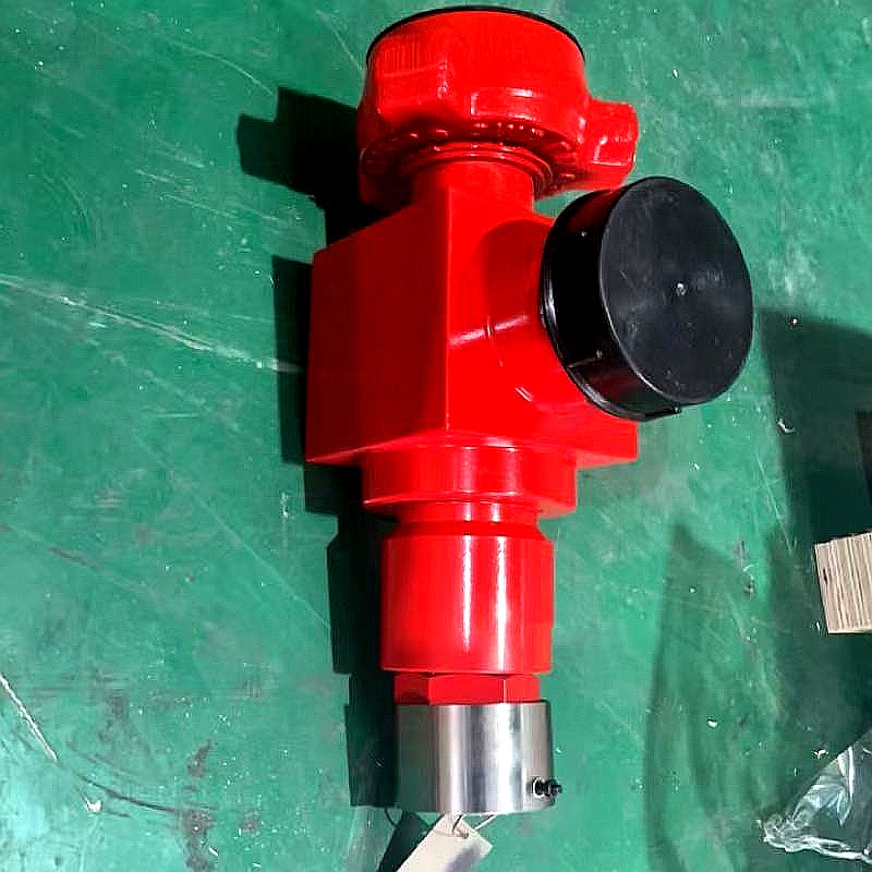
DEENPU 2″ 1502 Pressure Relief Valve — High Pressure Safety for Frac & Flowback Operations
The DEENPU 2″ 1502 Pressure Relief Valve is a critical safety device designed for high-pressure hydraulic fracturing (frac), flowback operations, well service, and stimulation applications. It is installed in the high-pressure piping system to protect pumps, manifolds, and surface equipment from overpressure conditions by automatically relieving excess pressure when the system pressure exceeds the preset relief set point.
The valve features a 2″ nominal bore with 1502 API hammer union end connections, providing quick and reliable make-up and break-out in the field. The 1502 union connection is the industry standard for high-pressure flowline and treating line connections in frac and well service operations, rated for working pressures up to 15,000 PSI. The valve body is forged from high-strength alloy steel and finished with a durable red paint coating for corrosion protection and visibility in the field.
DEENPU pressure relief valves are available with a wide range of set pressure settings from 6,000 PSI to 15,000 PSI, with standard set pressure increments available in 250 PSI or 500 PSI steps. The valve is designed to reseat automatically after the overpressure event has passed, or can be configured with a manual or remote reset mechanism depending on the application requirements. Each valve is factory-set and tested to the specified relief pressure, with a calibration certificate provided.
How the Pressure Relief Valve Works
The pressure relief valve performs a critical safety function in the high-pressure treating system during frac and flowback operations:
- Overpressure Protection — The relief valve is installed in the high-pressure treating line, typically downstream of the frac pumps and upstream of the wellhead. It is set to open at a predetermined pressure (the set pressure) that is below the maximum allowable working pressure (MAWP) of the downstream equipment. If a blockage occurs downstream (e.g., a sand plug, a closed valve, or a frozen flowline), the pump pressure will rise rapidly. When the pressure reaches the set pressure, the relief valve opens automatically, diverting the high-pressure fluid to a safe discharge location (typically a pit, tank, or flare system). This prevents the treating line, wellhead, or downstream equipment from rupturing due to overpressure. The set pressure is typically set at 10% below the MAWP of the lowest-rated component in the system, providing a safety margin.
- Automatic or Manual Reseat — When the overpressure condition is relieved and the system pressure drops below the set pressure, the valve reseats automatically, closing the flow path and returning the system to normal operation. The reseat pressure is typically set at 90-95% of the set pressure (a 5-10% blowdown). This prevents the valve from chattering (rapidly opening and closing) at pressures near the set point. For some applications, the valve may be configured with a manual reset mechanism that requires the operator to manually reseat the valve after it has opened. This is used in situations where the operator wants to inspect the system and confirm the cause of the overpressure before returning to normal operation. Remote reset options are also available for automated frac operations where the valve is operated from a control cabin.
- High-Pressure Fluid Diversion — The 2″ 1502 union connections allow the valve to be installed inline with standard frac treating iron (2″ or 3″ flowline) using hammer union couplings. The discharge side of the valve is typically connected to a relief line that runs to a safe discharge location. The valve is designed to handle the full flow rate of the treating line when open, with minimal backpressure. The flow capacity of the valve is rated in terms of the orifice area and the flow coefficient (Cv or Kv), which determines the maximum flow rate at a given overpressure. DEENPU 2″ relief valves are sized to handle the full output of a single frac pump or a portion of the total treating rate, depending on the system design. Multiple relief valves may be installed in parallel to handle the total treating rate of a multi-pump frac spread.
Key Features
Applications
- Hydraulic fracturing (frac) operations — Overpressure protection on the high-pressure treating line between frac pumps and wellhead
- Flowback operations — Safety relief on flowback manifold, choke manifold, and wellhead isolation systems
- Well stimulation and acidizing — Overpressure protection during acid stimulation, matrix acidizing, and hydraulic fracturing
- Well service and workover — Safety relief on well service pump lines, cementing lines, and nitrogen pump lines
- High-pressure pumping systems — Relief valve on discharge manifold of high-pressure pumps, cement pumps, and nitrogen pumps
- Manifold and treating iron systems — Overpressure protection on frac manifold, zipper manifold, and treating iron assemblies
- Pressure testing and hydrotesting — Safety relief during pressure testing of wellhead, BOP stack, and surface equipment
- Offshore platform frac and stimulation — Compact, high-pressure relief valve for offshore hydraulic fracturing and stimulation operations
Technical Specifications
| Parameter | Specification |
|---|---|
| Nominal Size | 2″ (50.8 mm) |
| End Connection | 2″ 1502 API Hammer Union (male x female) |
| Working Pressure | 15,000 PSI (103.4 MPa) maximum |
| Set Pressure Range | 6,000 PSI – 15,000 PSI (41.4 – 103.4 MPa) |
| Set Pressure Increment | 250 PSI or 500 PSI standard; custom increments available |
| Set Pressure Accuracy | +/- 3% of set pressure at 72°F (22°C) |
| Reseat Pressure | 90–95% of set pressure (5–10% blowdown) |
| Body Material | Forged alloy steel (AISI 4130 / 4140 standard) |
| Trim Material | Stainless steel or Inconel (for sour service) |
| Spring Material | Chrome-silicon alloy steel or Inconel X-750 |
| Seal Type | Metal-to-metal seat seal with O-ring backup |
| Operating Temperature | -20°F to 250°F (-29°C to 121°C) standard; high-temperature options available |
| Reset Type | Automatic reseat (standard); manual reset; remote reset (optional) |
| Flow Capacity | Rated Cv / Kv per orifice size; consult factory for specific application |
| Coating / Finish | Red epoxy paint (standard); other colors available |
| Weight (approximate) | 45–65 lbs (20–30 kg) depending on configuration |
| Standards | API 6A, API 16C, NACE MR0175 (for sour service) |
All specifications are standard configurations. Custom set pressures, temperature ranges, materials, and connection types are available on request. Contact DEENPU engineering for application-specific sizing and selection.
When Ordering, Please Specify
- Set PressureRequired relief set pressure in PSI or MPa. Specify exact set pressure (e.g., 10,000 PSI) or range (e.g., 8,000–12,000 PSI adjustable).
- End Connection Type2″ 1502 hammer union (standard). Other sizes and connection types (1502 x 2002, 2002 x 2002, threaded, flanged) available on request.
- Reset TypeAutomatic reseat (standard), manual reset (requires operator to reseat after opening), or remote reset (pneumatic or hydraulic actuator for remote operation).
- Body and Trim MaterialStandard alloy steel (AISI 4130/4140) body with stainless steel trim. For sour service, specify NACE MR0175 compliant materials (Inconel, 316 SS, or duplex stainless steel).
- Spring MaterialStandard chrome-silicon alloy steel spring. For high-temperature or sour service, specify Inconel X-750 or other high-temperature alloy spring.
- Service FluidWater, frac fluid (gel, slickwater, linear), nitrogen, acid, or other. Specify fluid composition for material and seal compatibility.
- Operating TemperatureMinimum and maximum ambient and fluid temperature. Standard range: -20°F to 250°F. Extended temperature ranges available.
- Flow Capacity RequirementRequired flow rate at set pressure or overpressure condition. Specify treating rate (bbl/min or m3/min) and fluid type for valve sizing.
- Discharge ConfigurationOpen discharge (standard), closed discharge to line, or flare connection. Specify discharge connection type and orientation.
- Certification RequirementsAPI 6A / 16C certification, material test certificates (MTC), hydrostatic test certificates, set pressure calibration certificate, NACE MR0175 compliance certificate, and third-party inspection (DNV, BV, SGS).
Custom Manufacturing & OEM Capability
- Non-Standard Set Pressure — Custom set pressures outside the standard 6,000–15,000 PSI range, including low-pressure relief (1,000–5,000 PSI) and ultra-high-pressure relief (15,000–20,000 PSI).
- Multiple Size and Connection Options — 1″ 1502, 2″ 1502, 3″ 1502, 2″ 2002, 3″ 2002, and other hammer union sizes. Threaded and flanged end connections also available.
- High-Temperature Service — Extended temperature range springs and seals for high-temperature frac and steam stimulation applications (up to 400°F / 204°C).
- Sour Service (H2S) — NACE MR0175 compliant materials: Inconel 625, 316L stainless steel, or duplex stainless steel body, trim, and springs for H2S-bearing service.
- Remote Operation and Monitoring — Pneumatic or hydraulic actuator for remote opening/closing. Pressure transmitter for remote monitoring of set pressure and valve status.
- Multiple Valve Manifold — Custom manifold assembly with multiple relief valves in parallel for high-flow-rate applications, with isolation valves for individual valve maintenance.
- Special Coating and Identification — Custom paint colors, RFID tagging, serialized identification, and electronic calibration records for fleet management.
- Complete Safety System — Relief valve supplied as part of a complete wellhead safety system including pressure gauges, transducers, ESD valves, and control system.
Quality Control & Testing Standards
- Material chemical composition and mechanical properties verified per batch. Tensile strength, yield strength, elongation, and hardness per API 6A.
- Body and bonnet magnetic particle inspection (MPI) and ultrasonic testing (UT) on all forgings per API 6A / 16C.
- Each valve shell hydrostatically tested to 1.5x rated working pressure per API 6A. Hold time and leak rate recorded on test certificate.
- Each valve seat hydrostatically tested to 1.1x rated working pressure in both directions. Zero leakage acceptance criterion.
- Set pressure calibration test performed on each valve using a calibrated hydraulic pressure test unit. Set pressure verified at ambient temperature and recorded on calibration certificate.
- Reseat pressure verification performed to confirm blowdown (reseating differential) is within specification (90–95% of set pressure).
- High-pressure gas test (optional) using nitrogen or helium at 80% of set pressure for critical applications. Leak detection by bubble test or pressure decay.
- Spring rate and load verification on each spring to ensure consistent set pressure and reseat performance.
- Dimensional inspection of bore diameter, union thread dimensions, face-to-face length, and overall dimensions per API 6A tolerances.
- Material test certificates (MTC) per EN 10204 3.1 provided for all pressure-bearing and structural components.
- Third-party inspection and certification by DNV, BV, SGS, or ABS available upon request.
Frequently Asked Questions
What is the difference between a pressure relief valve and a rupture disc?
A pressure relief valve is a reusable device that opens at a set pressure and reseats when the pressure drops, allowing the system to return to normal operation after the overpressure event. It can be tested, adjusted, and reused many times. A rupture disc (burst disc) is a one-time-use device that ruptures at a predetermined pressure, permanently opening the flow path. The rupture disc must be replaced after activation, requiring system shutdown. Pressure relief valves are preferred for frac and flowback operations because they allow the system to continue operating after a minor overpressure event (e.g., a brief pressure spike). Rupture discs are sometimes used as backup protection (in series with a relief valve) or in applications where zero leakage is required and the valve cannot be relied upon for absolute tightness. DEENPU offers both pressure relief valves and rupture disc assemblies for frac and well service applications.
How do I select the correct set pressure for my relief valve?
The set pressure should be selected based on the maximum allowable working pressure (MAWP) of the lowest-rated component in the system downstream of the relief valve. The general rule is: set pressure = MAWP – 10% margin (or MAWP – 500 PSI, whichever is greater). For example, if the treating iron, wellhead, and downstream equipment are rated for 15,000 PSI, the relief valve set pressure should be 13,500 PSI (10% below MAWP) or 14,500 PSI (500 PSI below MAWP), depending on the company policy and regulatory requirements. The set pressure must also be above the maximum normal operating pressure to prevent nuisance opening during normal operations. For frac operations, the normal treating pressure is typically 8,000–12,000 PSI, so a set pressure of 13,500 PSI on a 15,000 PSI system provides adequate protection without nuisance opening. The set pressure should be clearly marked on the valve body and recorded in the well file. The valve should be tested and recalibrated annually or after any activation event.
What is the difference between automatic reset and manual reset relief valves?
An automatic reset relief valve reseats (closes) automatically when the system pressure drops below the reseat pressure (typically 90-95% of the set pressure). This is the standard configuration for frac and flowback operations because it allows the system to return to normal operation immediately after the overpressure event is relieved. Automatic reset is essential for continuous operations where the pump spread is running and the operator does not want to shut down the entire system for a minor pressure spike. A manual reset relief valve requires the operator to physically reset the valve (typically by pushing a reset button or lever) after it has opened. This is used in applications where the operator wants to inspect the system and confirm the cause of the overpressure before returning to normal operation. Manual reset is sometimes required by company safety policies for critical wellhead protection or in situations where the overpressure may indicate a serious system failure that should be investigated before resuming operations. Remote reset valves can be reset from a control cabin using a pneumatic or hydraulic actuator, combining the safety of manual reset with the convenience of remote operation.
How often should the relief valve be tested and recalibrated?
API 6A and industry best practices recommend that pressure relief valves be tested and recalibrated at least annually, or more frequently depending on the service conditions. Valves that have been activated (opened) should be tested and recalibrated before returning to service. The test procedure involves: (1) removing the valve from the line; (2) connecting it to a calibrated hydraulic test unit; (3) gradually increasing the pressure until the valve opens; (4) recording the opening pressure and comparing it to the set pressure; (5) verifying the reseat pressure; (6) adjusting the set pressure if it has drifted by more than 3%; (7) documenting the test results on a calibration certificate. Factors that can cause set pressure drift include: spring fatigue from repeated cycling, high-temperature exposure, corrosion of the seat or spring, and mechanical damage from vibration or impact. Valves in high-cycle service (e.g., daily frac operations) may require testing every 3-6 months. DEENPU provides factory recalibration services and can supply spare springs and trim kits for field maintenance.
Can the relief valve be used in sour gas (H2S) service?
Yes, DEENPU pressure relief valves can be configured for sour gas (H2S) service by selecting NACE MR0175 compliant materials for all wetted components. Standard carbon steel bodies and chrome-silicon springs are susceptible to sulfide stress cracking (SSC) in H2S-bearing environments. For sour service, the following material upgrades are required: Body and bonnet — NACE-compliant low-alloy steel or stainless steel (e.g., AISI 4130 with NACE hardness limits, or 316L stainless steel). Trim (seat, disc, stem) — Inconel 625, 316L stainless steel, or duplex stainless steel. Spring — Inconel X-750 or other NACE-compliant high-temperature alloy spring. Seals — HNBR, Viton (FKM), or PTFE seals rated for H2S service. The valve must be marked “SOUR SERVICE” and supplied with a NACE MR0175 compliance certificate. It is critical to specify sour service at the time of ordering because the material selection affects the valve design, cost, and lead time. H2S concentration, partial pressure, and temperature must be provided for proper material selection.
What certifications do your pressure relief valves carry?
DEENPU 2″ 1502 Pressure Relief Valves are manufactured in accordance with API 6A (Specification for Wellhead and Christmas Tree Equipment) and API 16C (Specification for Choke and Kill Systems). Each valve is supplied with a comprehensive documentation package including: material test certificate (chemical composition and mechanical properties), hydrostatic test certificate (shell test at 1.5x working pressure and seat test at 1.1x working pressure), set pressure calibration certificate (verified on a calibrated test unit), dimensional inspection report, and NDT reports (MPI/UT on body and bonnet). For sour service applications, a NACE MR0175 / ISO 15156 compliance certificate is provided. Material traceability is maintained from raw material through forging, heat treatment, machining, assembly, testing, and final inspection. Each valve is serialized and marked with the serial number, set pressure, date of manufacture, and material grade. Third-party inspection and certification by DNV, BV, SGS, or ABS is available on request for projects requiring classification society approval or customer-specific quality assurance protocols.
Request a Quote — 2″ 1502 Pressure Relief Valve
Send your frac or flowback system specifications and we will recommend the optimal relief valve configuration, set pressure, and material selection with a complete proposal including pricing, delivery schedule, and test certificates within 48 hours.
- EMAILSALES@DEENPU-MACHINERY.COM
- WHATSAPP+86-15806284962
- RESPONSEQuotation within 48 hours
Include: Set pressure, end connection type, reset type (auto/manual/remote), service fluid, operating temperature, flow capacity requirement, and certification requirements.
About Us
 Our company has been in the oil & gas drilling equipment industry for over more years, We are here to serve all your drilling equipment needs.